

OR Circuit Explained

OR Circuit Explained: 7 Powerful Facts to Master OR Gates and Digital Logic

OR Circuit Explained: 7 Powerful Facts to Master OR Gates and Digital Logic

Understanding an OR circuit is an important step for anyone learning electronics, computer science, or digital systems. OR circuits are one of the basic building blocks of digital logic and are used in many devices that process information.

Many beginners get confused because the word “or” has a different meaning in everyday language compared to digital electronics. In normal conversation, “or” often means choosing between options. In digital logic, an OR circuit follows a specific rule: the output becomes active when one or more inputs are active.

This complete guide explains OR circuits, OR gates, digital logic, truth tables, symbols, working methods, applications, and common mistakes in an easy way.


Quick Answer: OR Circuit Explained

An OR circuit is a digital logic circuit that produces an output when at least one input signal is ON or HIGH.

Simple rule:

One active input is enough to activate the output.

If all inputs are OFF, the output remains OFF.
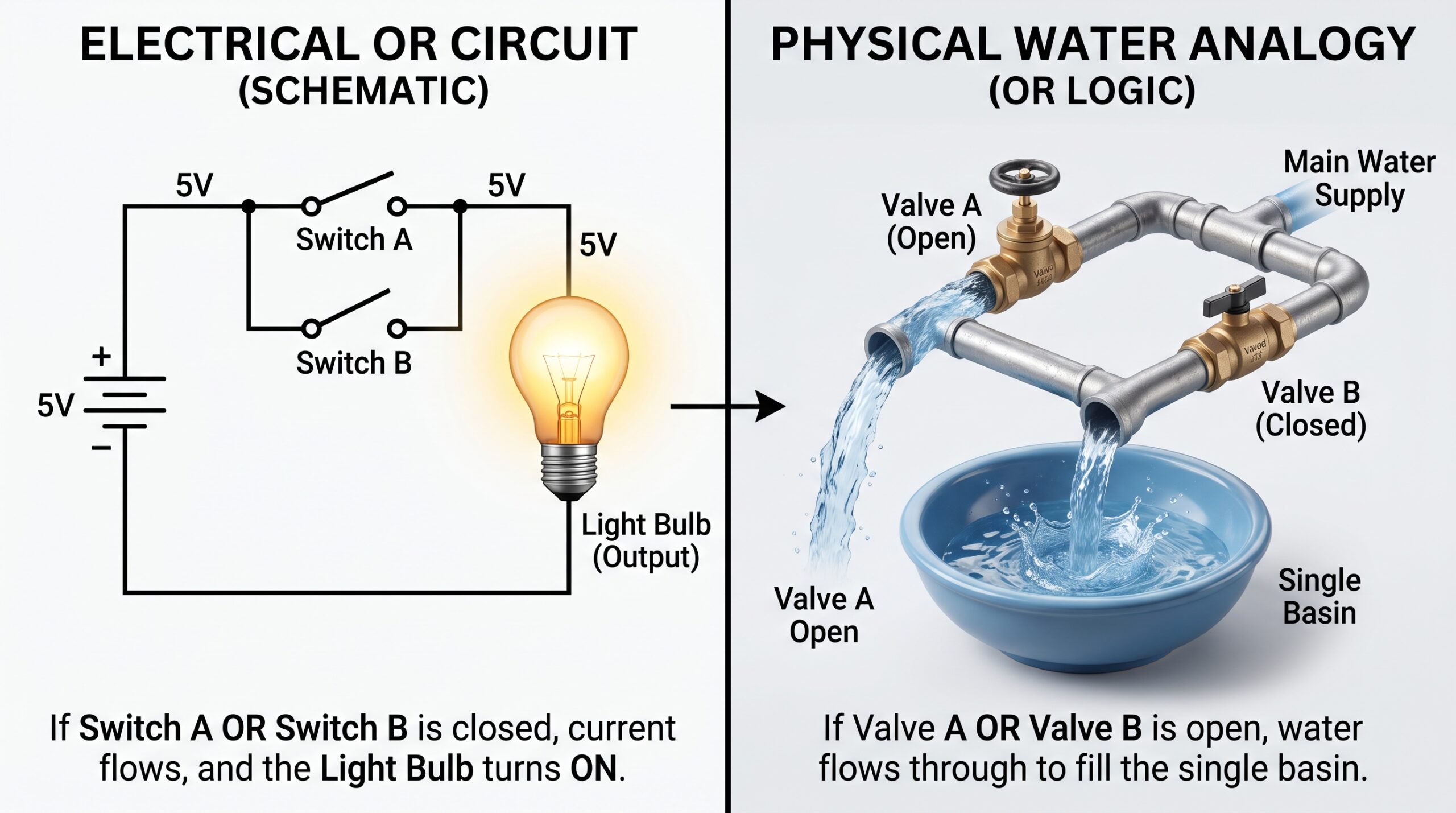
OR Circuit Explained


1. What Is an OR Gate?

An OR gate is a basic logic gate used to perform an OR operation in digital electronics.

It normally contains:

• Two or more inputs
• One output

The output depends on the condition of the inputs.

Examples:

Input A = ON
Input B = OFF

Output = ON

Input A = OFF
Input B = OFF

Output = OFF

Key insight: An OR gate responds when any input receives a signal.


2. How Does an OR Circuit Work?

An OR circuit works using Boolean logic, a system used by computers and electronic devices to process information.

Digital systems use:

• 1 = ON or TRUE
• 0 = OFF or FALSE

The OR operation follows this principle:

• If any input is 1, the output is 1
• If all inputs are 0, the output is 0

This simple rule allows electronic systems to make decisions based on multiple conditions.

3. OR Gate Truth Table Explained

A truth table shows all possible input combinations and their outputs.

Input A Input B Output
0 0 0
0 1 1
1 0 1
1 1 1

From this table:

• Both inputs OFF gives an OFF output
• Any input ON gives an ON output

This makes OR gates useful for systems with multiple activation points.


4. OR Circuit Symbol and Logic Expression

In circuit diagrams, an OR gate has a curved shape with multiple input lines and one output line.

The basic Boolean expression is:

A OR B = Y

or:

A + B = Y

Where:

• A and B represent inputs
• Y represents the output

The plus symbol does not mean normal mathematical addition. It represents the OR operation.


5. Real World Applications of OR Circuit Explained

Security Systems

An alarm system may activate when:

• A door sensor detects opening
• A window sensor detects movement

Either condition can trigger the alarm.

🎯 Lesson: OR circuits allow multiple ways to activate one system.


Automatic Control Systems

A machine may start when:

• Button A is pressed
• Button B is pressed

Both buttons provide possible control options.

🎯 Lesson: OR logic makes systems more flexible.


Computer Technology

Computers use OR gates inside digital circuits to process information and perform logical operations.

🎯 Lesson: OR circuits are essential parts of modern electronics.


6. OR Gate vs AND Gate: Main Difference

Feature OR Gate AND Gate
Output Activates When Any input is ON All inputs are ON
Logic Meaning One condition is enough Every condition is needed
Example A or B activates system A and B activate system

Easy memory:

OR = One is enough

AND = All are needed

7. Common Mistakes About OR Circuit Explained

Mistake 1: Thinking OR means only one choice

Why it happens:
People use “or” differently in everyday language.

Correction:
In digital logic, OR allows one or multiple active inputs.


Mistake 2: Confusing OR with AND logic

Why it happens:
Both are common logic gates.

Correction:
OR needs any active input, while AND requires all inputs.


Mistake 3: Thinking 1 and 0 are normal numbers

Why it happens:
The symbols look mathematical.

Correction:
They represent digital states like ON and OFF.


Memory Trick: OR Circuit

Remember:

OR = Output Responds

If one input responds, the output responds too.


Expert Insight: Why OR Circuits Are Important

OR circuits are one of the most important foundations of digital electronics. They allow systems to combine different signals and respond when multiple conditions are possible.

From simple switches to advanced processors, OR gates help electronic devices make logical decisions.

Learning OR circuits also helps students understand larger topics such as computer hardware, programming logic, and digital system design.

Conclusion: OR Circuit Explained

An OR circuit is a digital logic circuit that produces an output when at least one input is active.

The main concept is simple:

Any active input can turn the output ON.

Understanding OR gates, truth tables, and digital logic creates a strong foundation for electronics and computer technology.


Scroll to Top