
NOT OR Gate Explained: 7 Powerful Facts to Master Logic Gates and Digital Circuits
Understanding a NOT OR gate can be confusing for beginners because it combines two important concepts in digital electronics: the NOT gate and the OR gate. These logic gates are basic building blocks used in computers, electronic devices, and digital systems.
Many learners search for NOT OR gate because they want to understand how combined logic operations work. The confusion usually comes from the fact that a NOT gate reverses a signal, while an OR gate produces an output when any input is active.
Although they are simple individually, combining them creates a different logic function called a NOR gate.
This guide explains the NOT OR gate, its meaning, working principle, truth table, Boolean expression, applications, and common mistakes in a simple way.
Quick Answer: Not or Gate explained
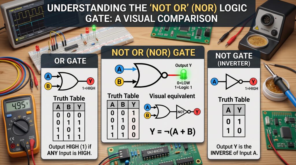
A NOT OR gate, also called a NOR gate, is a combination of an OR gate followed by a NOT gate.
It gives an output of 1 only when all inputs are 0.
Simple rule:
OR first, then NOT the result.
If any input becomes ON, the output becomes OFF.
What Is an OR Gate?
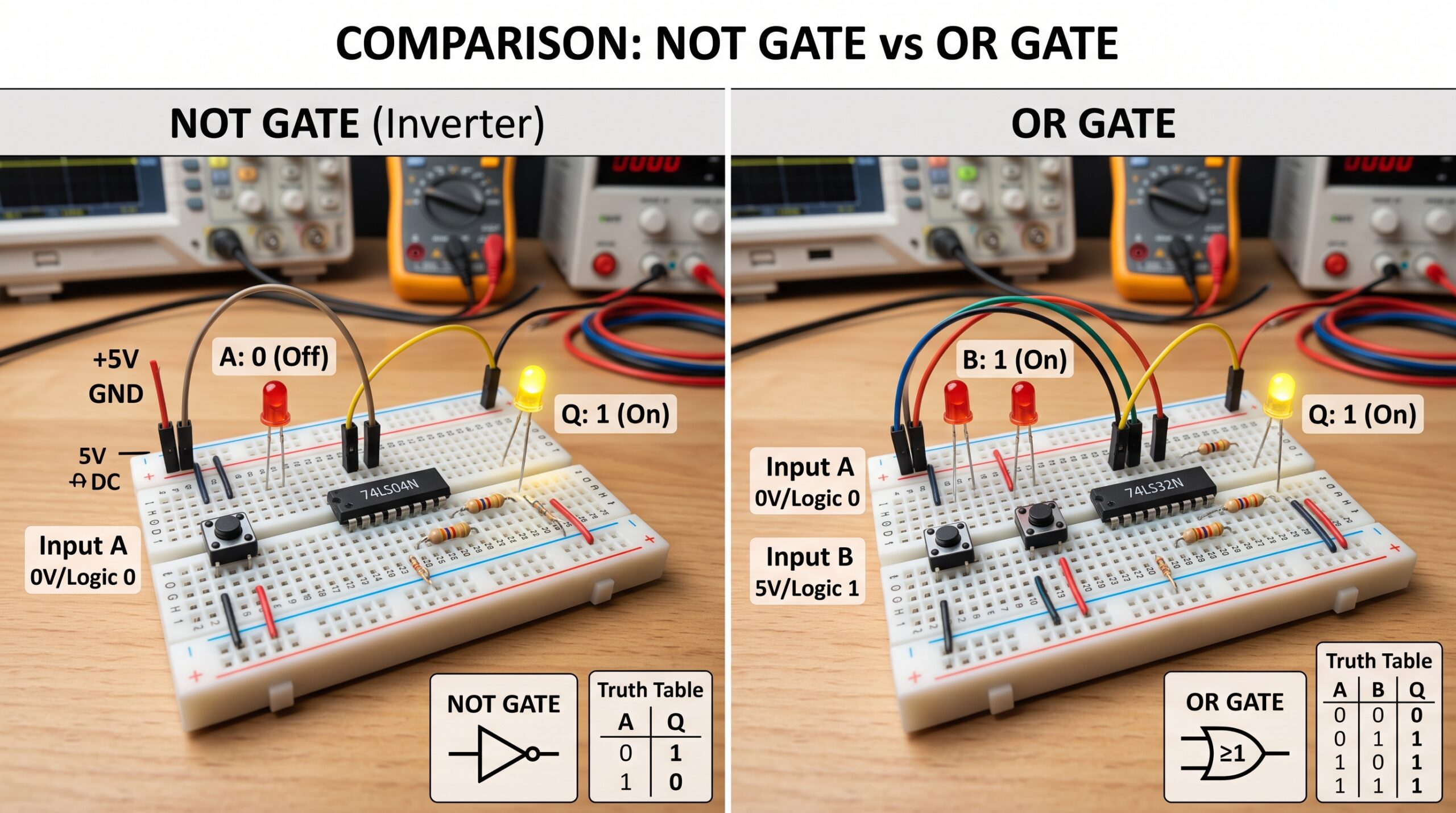
An OR gate is a basic logic gate that produces an output when one or more inputs are active.
Example:
Input A = 1
Input B = 0
Output = 1
The OR gate follows this rule:
Any input ON = Output ON
OR gates are commonly used in digital circuits where multiple conditions can activate a system.
What Is a NOT Gate?
A NOT gate is a logic gate that reverses the input signal.
It is also called an inverter.
Examples:
Input = 1
Output = 0
Input = 0
Output = 1
The NOT gate simply changes ON to OFF and OFF to ON.
How Does a NOT OR Gate Work?
A NOT OR gate combines both operations.
Step 1:
The OR gate checks the inputs.
Step 2:
The NOT gate reverses the OR output.
Example:
Input A = 0
Input B = 0
OR output = 0
NOT changes it:
Final output = 1
Key insight: A NOR gate only gives a TRUE output when every input is FALSE.
NOT OR Gate Truth Table
| Input A | Input B | OR Output | NOR Output |
|---|---|---|---|
| 0 | 0 | 0 | 1 |
| 0 | 1 | 1 | 0 |
| 1 | 0 | 1 | 0 |
| 1 | 1 | 1 | 0 |
The table shows that the output is ON only when both inputs are OFF.
NOT OR Gate Boolean Expression
The Boolean expression for a NOT OR gate is:
Y = NOT (A + B)
Where:
• A and B are inputs
• + represents OR operation
• Y represents output
The NOT symbol reverses the OR result.
Real World Applications of NOT OR Gates
Example 1: Safety Systems
A machine may operate only when:
• No warning signal is active
• No emergency condition exists
🎯 Lesson: NOR logic can represent “nothing is active.”
Example 2: Digital Memory Circuits
NOR gates are used in some electronic memory designs.
🎯 Lesson: Logic gates help computers store and process information.
Example 3: Control Systems
A system may activate only when multiple inputs remain inactive.
🎯 Lesson: NOR gates are useful for condition checking.
NOT OR Gate vs OR Gate: Main Difference
| Feature | OR Gate | NOT OR Gate (NOR) |
|---|---|---|
| Output ON When | Any input is ON | All inputs are OFF |
| Operation | Normal OR | OR followed by NOT |
| Logic Function | Addition of conditions | Reversal of OR result |
| Output Behavior | More active inputs increase output | Any active input turns output off |
Common Mistakes About Not or Gate explained
Mistake 1: Thinking NOR is the same as OR
Why it happens:
Both use the same inputs.
Correction:
NOR reverses the OR output.
Mistake 2: Forgetting the NOT operation
Why it happens:
The OR part is easier to notice.
Correction:
Always remember:
OR result → Reverse it
Mistake 3: Assuming output turns ON with active inputs
Why it happens:
That is true for OR gates.
Correction:
NOR works the opposite way.
Memory Trick: NOT OR Gate
Remember:
NOR = No OR
If there is any OR condition happening, the output turns OFF.
Expert Insight: Why NOT OR Gates Matter
NOT OR gates are important because they create a universal logic function. In digital electronics, NOR gates can be used to build other types of logic circuits.
They are used in:
• Computers
• Digital processors
• Control systems
• Electronic devices
Understanding NOR logic helps students build a foundation for advanced topics like circuit design and computer architecture.
Conclusion: NOT OR Gate Explained
A NOT gate, or NOR gate, is a logic gate that reverses the output of an OR gate.
The main rule is simple:
The output is ON only when all inputs are OFF.
Learning how NOT OR gates work helps you understand digital logic, electronic circuits, and the technology behind modern devices.
